Background
Accessibility and quality. A friend of mine is a budding force who works as a staff writer for a TV series in LA. While he was studying, he found trouble accessing an accurate, portable, controllable and affordable (<$200) camera slider – so I set out to build one for him and others in his position.
Results
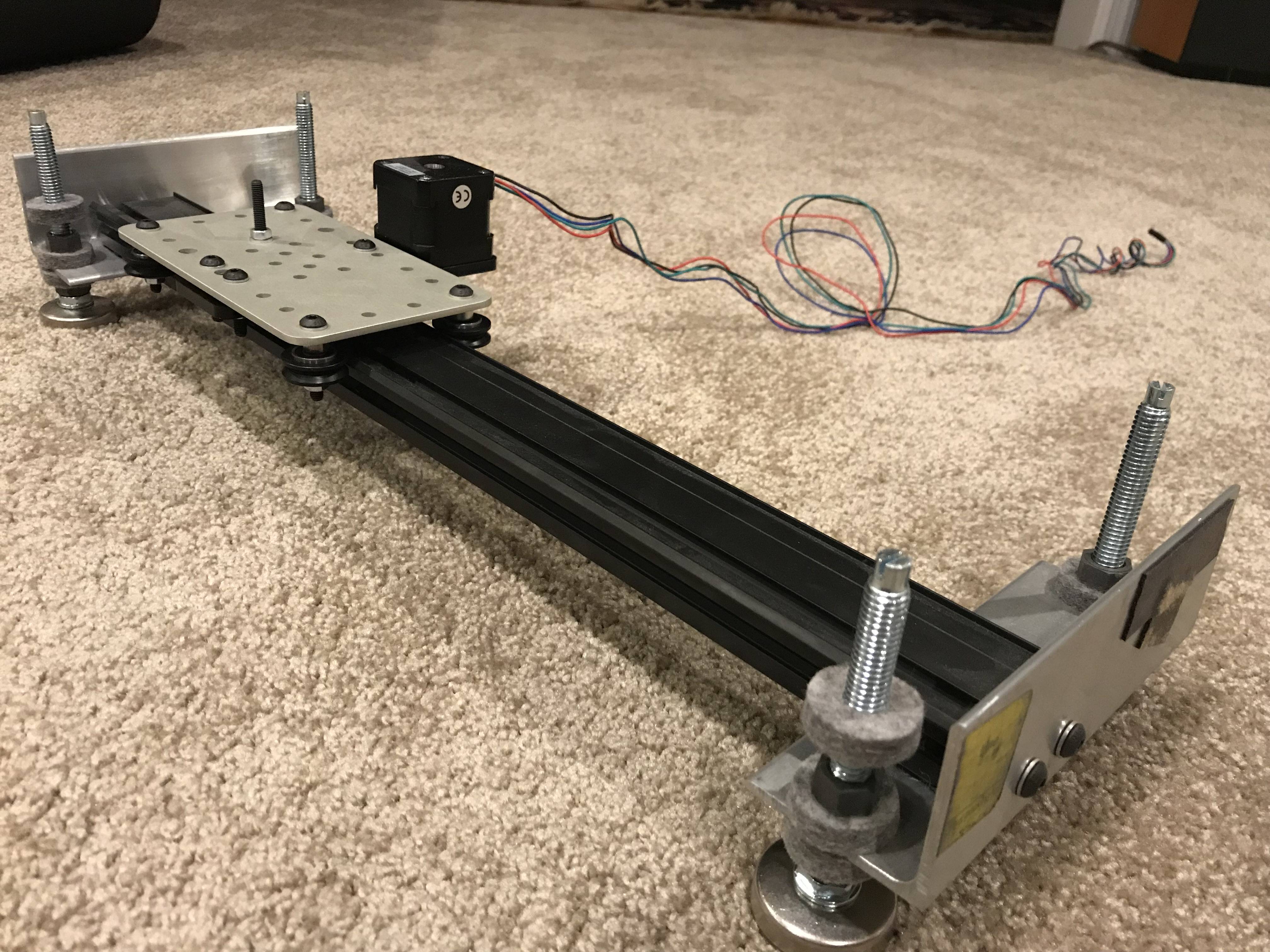
Ultimately, I designed and built a camera slider with 400µm accuracy. The overall system cost was ~$120, but if manufactured could be less than $100. Using Python commands, the slider could map certain functions (oscillatory, ramp by velocity, etc.), which consequently could be directed to travel an exact distance, direction and speed.
The design process was organized and methodical, following the “Design for Purpose” model of thinking. Material selection, drive systems and design constraints were all verified through a rigorous error budgeting process.
The slider was actuated linearly by a belt-drive system, using a timing drive pulley and two smooth surface idler pulleys for stability, and was designed such that a 150 pound object could be driven by the belt before the neoprene belt would come close to ripping. Ultimately, the life of the bearing and belt far exceeded the user’s requirements, and the stress applied to the belt was under 11% of the belt’s ultimate tensile strength. A micro-controller, python code, stepper motor, timing belt, CNC machining, 3D printing and laser cutting were utilized for this project.
Major Design Considerations
Precision Camera Slider – Project Catalogue

Bearing Design Analysis